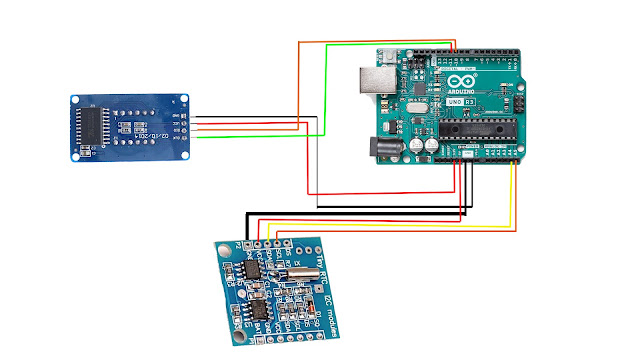
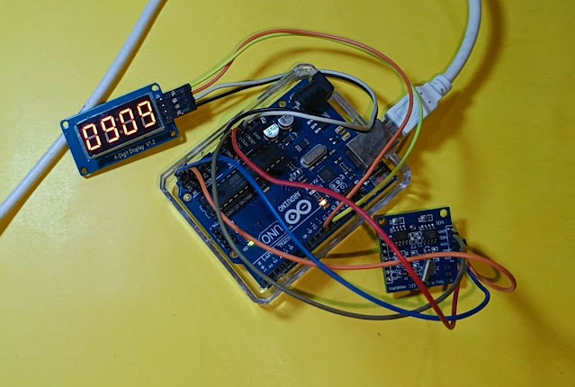
Digital clock using Arduino UNO , TM1637 4-digit 7 segment display and DS1307 RTC module. Here I show you how to make a simple digital clock using Arduino UNO very easily.
TM1637 4-digit 7 segment display :- https://amzn.to/3R3KC3p
DS1307 RTC module:- https://amzn.to/3dPDfyc
Arduino UNO:- https://amzn.to/3KcNfxR
Jumper Wire:- https://amzn.to/3KcBIyH
const int data = 10;
uint8_t digits[] = { 0x3f, 0x06, 0x5b, 0x4f, 0x66, 0x6d, 0x7d, 0x07, 0x7f, 0x6f };
void setup()
{
setupInterrupt();
pinMode(clock, OUTPUT);
pinMode(data, OUTPUT);
start();
writeValue(0x8c);
stop();
write(0x00, 0x00, 0x00, 0x00);
}
byte tcnt2;
// set current time by editing the values at line 16 and 17
unsigned long int setMinutes = 9; // set minutes
unsigned long int setHours = 9; // set hours
unsigned long time = (setMinutes * 60 * 1000) + (setHours * 3600 *1000);
void setupInterrupt()
{
TIMSK2 &= ~(1<<TOIE2);
TCCR2A &= ~((1<<WGM21) | (1<<WGM20));
TCCR2B &= ~(1<<WGM22);
ASSR &= ~(1<<AS2);
TIMSK2 &= ~(1<<OCIE2A);
TCCR2B |= (1<<CS22) | (1<<CS20);
TCCR2B &= ~(1<<CS21);
tcnt2 = 131;
TCNT2 = tcnt2;
TIMSK2 |= (1<<TOIE2);
}
ISR(TIMER2_OVF_vect) {
TCNT2 = tcnt2;
time++;
time = time % 86400000;
}
void loop()
{
unsigned long t = (unsigned long)(time/1000);
uint8_t minutes = (byte)((t / 60) % 60);
uint8_t hours = (byte)((t / 3600) % 24);
uint8_t seconds = (byte)(t % 60);
write(digits[hours / 10], digits[hours % 10] | ((seconds & 0x01) << 7), digits[minutes / 10], digits[minutes % 10]);
}
void write(uint8_t first, uint8_t second, uint8_t third, uint8_t fourth)
{
start();
writeValue(0x40);
stop();
start();
writeValue(0xc0);
writeValue(first);
writeValue(second);
writeValue(third);
writeValue(fourth);
stop();
}
void start(void)
{
digitalWrite(clock,HIGH);
digitalWrite(data,HIGH);
delayMicroseconds(5);
digitalWrite(data,LOW);
digitalWrite(clock,LOW);
delayMicroseconds(5);
}
void stop(void)
{
digitalWrite(clock,LOW);
digitalWrite(data,LOW);
delayMicroseconds(5);
digitalWrite(clock,HIGH);
digitalWrite(data,HIGH);
delayMicroseconds(5);
}
bool writeValue(uint8_t value)
{
for(uint8_t i = 0; i < 8; i++)
{
digitalWrite(clock, LOW);
delayMicroseconds(5);
digitalWrite(data, (value & (1 << i)) >> i);
delayMicroseconds(5);
digitalWrite(clock, HIGH);
delayMicroseconds(5);
}
digitalWrite(clock,LOW);
delayMicroseconds(5);
pinMode(data,INPUT);
digitalWrite(clock,HIGH);
delayMicroseconds(5);
bool ack = digitalRead(data) == 0;
pinMode(data,OUTPUT);
return ack;
}


Comments
Post a Comment